VSzA techblog

How to recalibrate the LCD of a Singer XL 1000

2018-02-04

My wife bought a Singer XL-1000 for 20% the original price, since the LCD was taking touch input offset by such an amount that most of its functionality was unreachable. The previous owner coudln't fix the problem and was glad that someone took the machine away, and we were glad that we could buy a machine at a price point lower than what such a machine would worth for us as a hobbyist tool.

We started searching on the web, and while some people had this problem, no usable solutions were posted. The users manual was available online, but had no mention of such an option. There was also a service manual available, but it also lacked any direct description of the procedure. However, it had instructions on opening service mode features, which eventually led me to discover the steps described below. (See page 35 from latter link above.)

  1. Turn off the machine, if it's on.
  2. Push the start/stop switch (⬆) and while pressed, turn on the machine, and release the switch only after the welcome screen has appeared.
  3. Push the reverse feed stitching switch (↷) and while pressed, touch the screen and then release the switch.
  4. Now you're in screen calibration mode. A dot appears on the left, touch it as accurately as you can (for example by using a plastic fork gently).
  5. The dot will reappear on an other spot, repeat the above three times.
  6. After the fourth dot disappears, the screen will look empty. In this mode, wherever the screen is touched, a pixel appears. It's like a simple drawing program, but it also makes it possible to test whether the touchscreen works properly.
  7. Now the important final step: touch the utility button in the lower left corner of the screen, which saves the calibration data and confirms it with a beep. After this, the service mode UI apperas with numbers in frames, but you can just quit by turning the machine off.
  8. Turning the machine on without any button being pressed at the same time resumes normal operation.

Below are two images I cleaned up from the service manual that indicate the two steps necessary to enter the calibration mode.

First step

Second step


Ham radio vs. hacker communities

2017-12-26

I've spent my last 20 years learning about and playing with stuff that has electricity in them, and this led me into two communities: the one of hackers, and the one of ham/amateur radio enthusiasts. Although I managed to get closer to the latter only in the last 10 years, I found lots of similarities between these two groups – even though most people I know that belong to only one of these groups would be surprised at this thought.

The two communities started having a pretty big overlap in the last decades, especially with the widespread availability of Software Defined Radio (SDR), most notably RTLSDRs, an unintended feature of cheap DVB-T dongles with Realtek chipsets. This put radio experimentation within reach of hackers and resulted in unforeseen developments.

In a guest rant by Bill Meara, Hack-a-Day already posted a piece about the two communities being pretty close back in 2013, and there are a growing number of people like Travis Goodspeed who are pretty active and successful in both communities. Let's hope that this blog post will encourage more members of each community to see what the other scene can offer. In the sections below, I'll try to show how familiar “the other side” can be.

Subscenes

There are subsets in both groups defined by skill and/or specific interests within the scene, which map quite nice between these two groups.

  • On the one hand, those who master the craft and gain experience by making their own tools are held in respect: real hackers (can) write their own programs, and real ham radio enthusiasts build their own gear. Even though, in both scenes this was a big barrier to entry historically, which is getting easier as time goes by – but this is exactly why those who still experiment with new methods are usually respected within the community.

  • On the other hand, people whose sole method of operation is by using tools made by other people are despised as appliance operators in radio and script kiddies in hacker terms.

  • There are virtual environments that mock the real world technology, many hackers and ham radio operators have mixed feelings towards games like Uplink and apps like HamSphere respectively. Some say it helps to spread the word, some question their whole purpose.

  • Trolls can be found in both groups, which can hurt the most when newcomers meet this subset during their first encounter with the community. A close, somewhat overlapping group is those who deliberately cause disruptions for others: signal jamming is pretty similar to denial of service (DoS) attacks. Most members of both communities despise such acts, which is especially important since the relevant authorities are often helpless with such cases. Of course, this also leads to the eventual forming of lynch mobs for DoS kiddies and signal jammers alike.

  • Mysteries permeate both scenes, resulting in data collection and analysis. Ham radio enthusiasts monitor airwaves, while hackers run honeypots to gather information about what other actors, including governments, corporations, and people are up to. Campfire talk about such projects include subjects such as numbers stations and the Equation Group.

  • Although for different reasons, but in both fields, armed with knowledge and having the right equipment can help a lot in disaster scenarios, resulting in subscenes that deal with such situations, organizing and/or taking part in field days and exercises. Of course, both subscenes wouldn't be complete without the two extremes: people who believe such preparation is unnecessary, and people who falsely believe they're super important with imaginary (and sometimes self-made) uniforms, car decorations, reflective vests, etc.

  • Some people are fascinated by artificial limitations, treating them as challenges. In the hacker community, various forms of code golf aim at writing the shortest computer code that performs a specific task, while ham radio operators experiment with methods to convey a message between two stations while using a minimal amount of transmit power, such as WSPR or QRSS. Although not strictly part of the hacker community, demoscene also thrives on such challenges with demos running on old hardware and intros being limited to a specific amount of bytes (such as 32, 256, 4k, 64k).

  • While artificial limitations may seem competitive in themselves, some people get almost purely focused on competitions. Hackers have their wargames and capture the flag (CTF) events, while ham radio operators have various forms of contests, typically measuring the quantity and quality (such as distance, rareness) of contacts (QSOs). And in both cases, there are people who consider competitions the best thing in the hobby, there are those in the middle, considering it as a great way to improve your skills in a playful way, and of course, some question the whole purpose and feel that competitions like these are the reason why we can't have nice things™.

  • Both communities have people who prefer low-level tinkering. Some hackers like to jump deep into machine code and/or assembly, while some ham radio operators (especially in the QRP scene) prefer sending and receiving Morse code (CW) transmissions. Also, hackers and amateur radio enthusiasts alike have quite a few members (re)discovering, fixing and hacking old hardware, usually for no other obvious reason than “because I can”. In both groups, outsiders sometimes don't really understand, why anyone would do such things nowadays, while the real fans ask back “why not”.

Other similarities

  • Sharing knowledge is at the core of both communities, there are online and AFK meetups where anyone can show what they did, and newcomers can join the scene. In most places I know, these groups work in a meritocratic manner, focusing more on the technical content and less on people stuff. And this is important because both communities deal with things where having a local group of peers can help individual development a lot.

  • Sharing knowledge also means that both communities build a lot on and publish a lot of free software (FLOSS, free as in free speech). Most hackers nowadays have a GitHub repository with a subset of their projects published there, while ham radio constructors usually publish schematics and source code for their firmware, since both communities realize that remixing and improving other people's designs can lead to awesome results.

  • Another common core theme is searching for and overstepping boundaries and technical limitations. Just like shortwave bands given to amateur radio operators since professionals at the time considered it unusable, people considered buffer overflows as simply bugs rather than a possible method of arbitrary code execution. In both fields, talented members of the respective communities managed to disprove these statements, leading to technical development that benefited lots of people, even those outside these groups.

  • Both communities are centered around activities that can be done as a hobby, but also offer professional career paths. And in both cases, many technical developments that are used daily in the professional part of the scene started out as an experiment in the other, hobbyist part. Also, becoming a successful member of each community is pretty much orthogonal with having a college/university degree – that being said, such institutions can often give home to a small community of either group, examples at my alma mater include HA5KFU and CrySyS.

  • Activities of both groups is a common plot device in movies, and because of limited budgets and screentime, their depiction often lacks detail and sometimes even a slight resemblance to reality. This results in members of these communities having another source of fun, as collecting and pointing out such failures is pretty easy. For example, there are dedicated pages for collecting movies with characters using ham radio equipment and the popular security scanner Nmap alike.


CCCamp 2015 video selection

2015-08-24

(note: any similarity between this post and the one I made four years ago is not a coincidence)

The Chaos Communication Camp was even better than four years ago, and for those who were unable to attend (or just enjoyed the fresh air and presence of fellow hackers instead of sitting in the lecture room), the angels recorded and made all the talks available on the camp2015 page of CCC-TV.

I compiled two lists, the first one consists of talks I attended and recommend for viewing in no particular order.

  • Two members of CCC Munich – a hackerspace H.A.C.K. has a really good relationship with – presented Iridium Hacking, which showed that they continued the journey they published last December at the Congress. It's really interesting to see what SDRs make possible for hackers, especially knowing that the crew of MuCCC was the one that created rad1o, the HackRF-based badge they gave to every attendee.
  • Speaking of the rad1o, the talk detailing that awesome piece of hardware was also inspiring and included a surprise appearance of Michael Ossmann, creator of HackRF.
  • I only watched the opening and closing ceremonies from recording, but it was worth it. If you know the feeling of a hacker camp, it has some nice gems (especially the closing one), if you don't, it's a good introduction.
  • Mitch Altman's talk titled Hackerspace Design Patterns 2.0 also appeals to two distinct audiences; if you already run a hackerspace, it distills some of the experience he gathered while running Noisebridge, if you don't, it encourages to start or join one. It was followed by a pretty good workshop too, but I haven't seen any recording of that yet.
  • Like many others, my IT background covers way more than my hardware DIY skills, so Lieven's practical prototyping primer gave me 50 really handy tips so that I can avoid some of the mistakes he made over the last 10 years.
  • Last but not least, now that analog TV stations are being turned off in many countries, Elektra's talk titled Freifunk in TV-Whitespace shows not only solutions for transverting Wi-Fi signals into the 70 cm band, but also many advantages to motivate hackers doing so.

The second list consists of talks I didn't attend but am planning to watch now the camp is over.


Lighthouse with PWM using ATtiny22

2013-10-18

October 2013 update: added photos and corrected STK500 pinout

After visiting a new hobby craft shop, we decided to create a picture frame with a seashore theme, which included a lighthouse. I thought it would be nice to include a pulsating light to make it more realistic - and providing me with a challenge while Judit did the rest of the frame.

When I got my Atmel STK500, the guy I bought it from gave some AVR MCUs with it, so I preferred to use one of these instead of buying one. Based on size and the number of pins, I selected an ATtiny22, which could be used without an external oscillator at 1 MHz, which was more than enough for me. On the other hand, the ATtiny22 didn't have PWM, which meant that I had to do it from software. The hardware setup was the following.

Lighthouse controller schematics

An LED was put through the lighthouse after some drilling, and the pins were routed through the frame, protected by a plastic bottle cap whose 20% was cut. The controller was put on a board with a socket on the side for the LED pins, the completely painted final version is on the right.

Lighthouse frame assembly

Since I used PB0 to drive the LED, I defined the bit I had to use as LED_PIN, with the value 20 = 1. I used this first when I set the direction register (DDR) of port B to use PB0 as output.

DDRB |= LED_PIN;

The rest of the program is an endless loop that does the pulsating in two similar phases, increasing the duty cycle of the PWM from minimum to maximum and then doing the same in reverse.

uint8_t level, wait;
while (1) {
    for (level = 0; level < 255; level++) {
        for (wait = 0; wait < HOLD; wait++) {
            sw_pwm(level);
        }
    }
    for (level = 255; level > 0; level--) {
        for (wait = 0; wait < HOLD; wait++) {
            sw_pwm(level);
        }
    }
}

I defined HOLD to 16 based on experimentation, this value determines how long the light stays at a specific brightness level, so lowering this would make the frequency of the pulsating higher. I defined the actual PWM logic in an inlined function called sw_pwm that executes an amount of NOP instructions related to the PWM duty cycle and toggles the port state using the PORTB register.

inline static void sw_pwm(uint8_t fill) {
    uint8_t ctr = 0;
    for (ctr = 0; ctr < fill; ctr++) {
        asm("nop");
    }
    PORTB ^= LED_PIN;
    for (ctr = fill; ctr != 0; ctr++) {
        asm("nop");
    }
    PORTB ^= LED_PIN;
}

Compilation and conversion to Intel hex was pretty straightforward using GCC.

$ avr-gcc main.c -o main -O2 -DF_CPU=1000000 -mmcu=attiny22
$ avr-objcopy -j .text -j .data -O ihex main main.hex

Flashing however required two things to be taken care of.

  • AVRdude doesn't know about ATtiny22 by this name, however, the man page states that “AT90S2323 and ATtiny22 use the same algorithm”, so I used 2343 as the parameter to the -p (part) command line switch.

  • As David Cook wrote on the Robot Room ATtiny tutorial, using STK500 not only requires putting the ATtiny22 into the rightmost blue socket, but two additional pins needs to be connected: PB3 to XT1 and PB5 to RST.

Having done the above, the following command uploads the hex to the ATtiny.

$ avrdude -p 2343 -c stk500 -P /dev/ttyUSB0 -U flash:w:main.hex

Below is a photo of the completed product, click on the image to view an animated GIF version, source code is available under MIT license in my GitHub repository.

The completed lighthouse, click to play


Bootstrapping the CDC version of Proxmark3

2013-05-15

A few weeks ago I updated my working directory of Proxmark3 and found that Roel Verdult finally improved the USB stack by ditching the old HID-based one and using USB CDC. My only problem was that having a device running the HID bootloader and a compiled version of the CDC flasher caused a chicken-egg problem. I only realized it when running make flash-all resulted in the following error message.

client/flasher -b bootrom/obj/bootrom.elf armsrc/obj/osimage.elf armsrc/obj/fpgaimage.elf
Loading ELF file 'bootrom/obj/bootrom.elf'...
Loading usable ELF segments:
0: V 0x00100000 P 0x00100000 (0x00000200->0x00000200) [R X] @0x94
1: V 0x00200000 P 0x00100200 (0x00000e1c->0x00000e1c) [RWX] @0x298
Attempted to write bootloader but bootloader writes are not enabled
Error while loading bootrom/obj/bootrom.elf

I checked the flasher and found that it didn't recognize the -b command line switch because it expected a port name (like /dev/ttyACM0) as the first argument. So I needed an old flasher, but first, I checked if the flasher binary depended on any Proxmark3 shared object libraries.

$ ldd client/flasher
    linux-vdso.so.1 =>  (0x00007fff6a5df000)
    libreadline.so.6 => /lib/x86_64-linux-gnu/libreadline.so.6 (0x00007fb1476d9000)
    libpthread.so.0 => /lib/x86_64-linux-gnu/libpthread.so.0 (0x00007fb1474bd000)
    libstdc++.so.6 => /usr/lib/x86_64-linux-gnu/libstdc++.so.6 (0x00007fb1471b5000)
    libm.so.6 => /lib/x86_64-linux-gnu/libm.so.6 (0x00007fb146f33000)
    libgcc_s.so.1 => /lib/x86_64-linux-gnu/libgcc_s.so.1 (0x00007fb146d1d000)
    libc.so.6 => /lib/x86_64-linux-gnu/libc.so.6 (0x00007fb146992000)
    libtinfo.so.5 => /lib/x86_64-linux-gnu/libtinfo.so.5 (0x00007fb146769000)
    /lib64/ld-linux-x86-64.so.2 (0x00007fb147947000)

Since the above were all system libraries, I used an old flasher left behind from the ages before I had commit access to the Proxmark3 SVN repository.

$ /path/to/old/flasher -b bootrom/obj/bootrom.elf \
    armsrc/obj/osimage.elf armsrc/obj/fpgaimage.elf
Loading ELF file 'bootrom/obj/bootrom.elf'...
Loading usable ELF segments:
0: V 0x00100000 P 0x00100000 (0x00000200->0x00000200) [R X] @0x94
1: V 0x00200000 P 0x00100200 (0x00000e1c->0x00000e1c) [RWX] @0x298

Loading ELF file 'armsrc/obj/osimage.elf'...
Loading usable ELF segments:
1: V 0x00110000 P 0x00110000 (0x00013637->0x00013637) [R X] @0xb8
2: V 0x00200000 P 0x00123637 (0x00002c74->0x00002c74) [RWX] @0x136f0
Note: Extending previous segment from 0x13637 to 0x162ab bytes

Loading ELF file 'armsrc/obj/fpgaimage.elf'...
Loading usable ELF segments:
0: V 0x00102000 P 0x00102000 (0x0000a4bc->0x0000a4bc) [R  ] @0xb4

Waiting for Proxmark to appear on USB...
Connected units:
        1. SN: ChangeMe [002/007]
 Found.
Entering bootloader...
(Press and release the button only to abort)
Waiting for Proxmark to reappear on USB....
Connected units:
        1. SN: ChangeMe [002/008]
 Found.

Flashing...
Writing segments for file: bootrom/obj/bootrom.elf
 0x00100000..0x001001ff [0x200 / 2 blocks].. OK
 0x00100200..0x0010101b [0xe1c / 15 blocks]............... OK

Writing segments for file: armsrc/obj/osimage.elf
 0x00110000..0x001262aa [0x162ab / 355 blocks]................................................................................................................................................................................................................................................................................................................................................................... OK

Writing segments for file: armsrc/obj/fpgaimage.elf
 0x00102000..0x0010c4bb [0xa4bc / 165 blocks]..................................................................................................................................................................... OK

Resetting hardware...
All done.

Have a nice day!

After resetting the Proxmark3, it finally got recognized by the system as a CDC device, as it can be seen below on a dmesg snippet.

[10416.461687] usb 2-1.2: new full-speed USB device number 12 using ehci_hcd
[10416.555093] usb 2-1.2: New USB device found, idVendor=2d2d, idProduct=504d
[10416.555105] usb 2-1.2: New USB device strings: Mfr=1, Product=0, SerialNumber=0
[10416.555111] usb 2-1.2: Manufacturer: proxmark.org
[10416.555814] cdc_acm 2-1.2:1.0: This device cannot do calls on its own. It is not a modem.
[10416.555871] cdc_acm 2-1.2:1.0: ttyACM0: USB ACM device

The only change I saw at first was that the client became more responsive and it required the port name as a command line argument.

$ ./proxmark3 /dev/ttyACM0
proxmark3> hw version
#db# Prox/RFID mark3 RFID instrument                 
#db# bootrom: svn 699 2013-04-24 11:00:32                 
#db# os: svn 702 2013-04-24 11:02:43                 
#db# FPGA image built on 2012/ 1/ 6 at 15:27:56

Being happy as I was after having a working new CDC-based version, I started using it for the task I had in mind, but unfortunately, I managed to find a bug just by reading a block from a Mifare Classic card. It returned all zeros for all blocks, even though I knew they had non-zero bytes. I found the bug that was introduced by porting the code from HID to CDC and committed my fix, but I recommend everyone to test your favorite functionality thoroughly to ensure that changing the USB stack doesn't affect functionality in a negative way. If you don't have commit access, drop me an e-mail with a patch or open an issue on the tracker of the project.

Happy RFID hacking!


FFmpeg recipes for workshop videos

2013-01-23

In November 2012, I started doing Arduino workshops in H.A.C.K. and after I announced it on some local channels, some people asked if it could be recorded and published. At first, it seemed that recording video would require the least effort to publish what we've done, and while I though otherwise after the first one, now we have a collection of simple and robust tools and snippets that glue them together that can be reused for all future workshops.

The recording part was simple, I won't write about it outside this paragraph, but although the following thoughts might seem trivial, important things cannot be repeated enough times. Although the built-in microphones are great for lots of purposes, unless you're sitting in a silent room (no noise from machines nor people) or you already use a microphone with an amplifier, a microphone closer to the speaker should be used. We already got a cheap lavalier microphone with a preamplifier and 5 meters of cable, so we used that. It also helps if the camera operator has a headphone, so the volume level can be checked, and you won't freak out after importing the video to the PC that either the level is so low that it has lots of noise or it's so high that it becomes distorted.

I used a DV camera, so running dvgrab resulted in dvgrab-*.dv files. Although the automatic splitting is sometimes desireable (not just because of crippled file systems, but it makes it possible to transfer each file after it's closed, lowering the amount of drive space needed), if not, it can be disabled by setting the split size to zero using -size 0. It's also handy to enable automatic splitting upon new recordings with -autosplit. Finally, -timestamp gives meaningful names to the files by using the metadata recorded on the tape, including the exact date and time.

The camera I used had a stereo microphone and a matching stereo connector, but the microphone was mono, with a connector that shorted the right channel and the ground of the input jack, the audio track had a left channel carrying the sound, and a right one with total silence. My problem was that most software handled channel reduction by calculating an average, so the amplitude of the resulting mono track was half of the original. Fortunately, I found that ffmpeg is capable of powerful audio panning, so the following parameter takes a stereo audio track, discards the right channel, and uses the left audio channel as a mono output.

-filter_complex "pan=1:c0=c0"

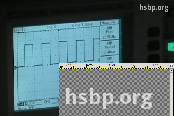
I also wanted to have a little watermark in the corner to inform viewers about the web page of our hackerspace, so I created an image with matching resolution in GIMP, wrote the domain name in the corner, and made it semi-transparent. I used this method with Mencoder too, but FFmpeg can handle PNGs with 8-bit alpha channels out-of-the-box. The following, combined command line adds the watermark, fixes the audio track, and encodes the output using H.264 into an MKV container.

$ ffmpeg -i input.dv -i watermark.png -filter_complex "pan=1:c0=c0" \
    -filter_complex 'overlay' -vcodec libx264 output.mkv

A cropped sample frame of the output can be seen below, with the zoomed watermark opened in GIMP in the corner.

hsbp.org watermark

I chose MKV (Matroska) because of the great tools provided by MKVToolNix (packaged under the same name in lowercase for Debian and Ubuntu) that make it possible to merge files later in a safe way. Merging was needed in my case for two reasons.

  • If I had to work with split .dv files, I converted them to .mkv files one by one, and merged them in the end.
  • I wanted to add a title to the beginning, which also required a merge with the recorded material.

I tried putting the title screen together from scratch, but I found it much easier to take the first 8 seconds of an already done MKV using mkvmerge, then placed a fully opaque title image of matching size using the overlay I wrote about above, and finally replace the sound with silence. In terms of shell commands, it's like the following.

ffmpeg -i input.mkv -i title.png -filter_complex 'overlay' -an \
    -vcodec libx264 title-img.mkv
mkvmerge -o title-img-8s.mkv --split timecodes:00:00:08 title-img.mkv
rm -f title-img-8s-002.mkv
ffmpeg -i title-img-8s-001.mkv -f lavfi -i "aevalsrc=0::s=48000" \
    -shortest -c:v copy title.mkv
rm -f title-img-8s-001.mkv

The first FFmpeg invocation disables audio using the -an switch, and produces title-img.mkv that contains our PNG image in the video track, and has no audio. Then mkvmerge splits it into two files, an 8 seconds long title-img-8s-001.mkv, and the rest as title-img-8s-002.mkv. Latter gets discarded right away, and a second FFmpeg invocation adds an audio track containing nothing but silence with a frequency (48 kHz) matching that of the recording. The -c:v copy parameter ensures that no video recompression is done, and -shortest discourages FFmpeg from trying to read as long as at least one input has data, since aevalsrc would generate silence forever.

Finally, the title(s) and recording(s) can be joined together by using mkvmerge for the purpose its name suggest at last. If you're lucky, the command line is as simple as the following:

$ mkvmerge -o workshop.mkv title.mkv + rec1.mkv + rec2.mkv

If you produced your input files using the methods described above, if it displays an error message, it's almost certainly the following (since all resolution/codec/etc. parameters should match, right?).

No append mapping was given for the file no. 1 ('rec1.mkv'). A default
mapping of 1:0:0:0,1:1:0:1 will be used instead. Please keep that in mind
if mkvmerge aborts with an error message regarding invalid '--append-to'
options.
Error: The track number 0 from the file 'dvgrab-001.mkv' cannot be
appended to the track number 0 from the file 'title.mkv'. The formats do
not match.

As the error message suggests, the order of the tracks can differ between MKV files, so an explicit mapping must be provided to mkvmerge for matching the tracks befor concatenation. The mapping for the most common case (a single audio and a single video track) is the following.

$ mkvmerge -o workshop.mkv t.mkv --append-to '1:0:0:1,1:1:0:0' + r1.mkv

I've had a pretty good experience with H.264-encoded MKV files, the size stayed reasonable, and most players had no problem with it. It also supports subtitles, and since YouTube and other video sharing sites accept it as well, with these tips, I hope it gets used more in recording and publishing workshops.


Connecting Baofeng UV-5R to a Linux box

2012-12-23

Ever since I bought my Baofeng UV-5R handheld VHF/UHF FM transceiver, I wanted to hook it up to my notebook – partly to populate the channel list without fighting the crippled UI, partly out of curiosity. First, I had to build a cable, since I didn't receive one in the package, and it would've cost at least around 20 bucks to get my hands on one – plus the delay involved in postal delivery. In a Yahoo! group, jwheatleyus mentioned the following pinout:

  • 3.5mm Plug Programming Pins
    • Sleeve: Mic – (and PTT) Rx Data
    • Ring: Mic +
    • Tip: +V
  • 2.5mm Plug
    • Sleeve: Speaker – (and PTT) Data GND
    • Ring: Tx Data
    • Tip: Speaker +
  • Connect Sleeve to Sleeve for PTT

I took apart the headset bundled with the gear, and verified this pinout in case of the Mic/Speaker/PTT lines with a multimeter, so I only had to connect these pins to the notebook. Since I already had an FTDI TTL-232R-5V cable lying around for use with my Diavolino (actually, I won both of them on the LoL shield contest at 27C3), I created a breakout board that can be connected to the radio, and had pin headers just in the right order for the FTDI cable and two others for speaker and mic lines. The schematic and the resulting hardware can be seen below.

Baofeng UV-5R breakout board

With the physical layer ready, I only had to find some way to manipulate the radio using software running on the notebook. While many software available for this radio is either closed and/or available for Windows only, I found Chirp, a FLOSS solution written in Python (thus available for all sane platforms) which – as of this writing – could access Baofeng UV-5R in the experimental daily builds. Like most Python software, Chirp doesn't require any install procedures either, downloading and extracting the tarball led to a functional and minimalistic GUI. First, I set the second tuner to display the name of the channel, and uploaded a channel list with the Hármashatár-hegy SSTV relay (thus the name HHHSSTV) at position 2, with the following results.

HHHSSTV channel stored on Baofeng UV-5R

I could also access an interesting tab named other settings that made it possible to edit the message displayed upon startup and limit the frequency range in both bands.

Other settings and their effect on Baofeng UV-5R

Although Chirp states that the driver for UV-5R is still experimental, I didn't have any problems with it, and as it's written in Python, its code is readable and extensible, while avoiding cryptic dependencies. It's definitely worth a try, and if lack of PC connectivity without proprietary software was a reason for you to avoid this radio, then I have good news for you.


Leaking data using DIY USB HID device

2012-10-29

Years ago, there was a competition, where contestants had to extract date out of a system that was protected by a state-of-the-art anti-leaking solution. Such challenges are based on the fact that private information should be available for use on a protected computer, but it must stay within the physical boundaries of the system. Obvious methods like networking and removable storage devices are usually covered by these mechanisms, but as with DRM, it's difficult – if not impossible – to think of every possibility. For example, in the aforementioned challenge, some guys used the audio output to get a file off the box – and when I heard about the Little Wire project, I started thinking about a new vector.

The requirements for my solution was to be able to extract data out of a

  • Windows 7 box
  • with no additional software installed
  • logged in as non-administrative account
  • that only allows a display, a keyboard and a mouse to be connected.

My idea was to use a USB HID device, since these can be connected to such system without additional drivers or special privileges. I've already built such a device for interfacing JTAG using an Arduino clone and V-USB, so I could reuse both hardware and experience, but avoid using an external programmer. The V-USB library made it possible for me to create an USB device without buying purpose-built hardware, by bit-banging the USB protocol with the general-purpose input and output pins of an AVR ATmega328 microcontroller. When used correctly, the AVR device shows up as a regular keyboard in the Windows 7 devices dialog.

USBpwn in the Windows 7 devices dialog

Keyboard was a logical choice for data extraction, since it was the only part of the HID specification that has a three bit wide output channel that's controllable without drivers and/or administrative privileges: the NUM, CAPS and SCROLL lock status LEDs. I've crafted a simple protocol that used NUM and CAPS as two data bits and SCROLL as a clock signal. When the SCROLL LED was on, the other two LEDs could be sampled for data. The newline (that could be achieved by “pressing” the Enter/Return key, since we're already “keyboards”) was the acknowledgement signal, making the protocol fully synchronous. For example, the bits 1101 could be sent in the following way:

            __________________________________
   NUM ____/
                               _______________
  CAPS _______________________/
                ______            ______
SCROLL ________/      \__________/      \_____

                  01                11

On the Windows host, an extractor agent was needed, that performed the transfer using the following code snippet:

set_lock(NUM,  (frame & 0x01) == 0x01);
set_lock(CAPS, (frame & 0x02) == 0x02);
set_lock(SCROLL, 1);
getchar();
toggle_key(SCROLL);

Bits were sent from LSB to MSB, n bytes were sent from 0 to n-1, stored at the nth position in the EEPROM. I tried using an SD card to store the data received, but it conflicted with the V-USB library, so I had to use the built-in EEPROM – the MCU I used was the ATmega328, which had 1 kbyte of it, which limited the size of the largest file that could be extracted.

Of course, the aforementoned agent had to be placed on the Windows box before transmitting file contents. The problem was similar to using dumb bindshell shellcodes to upload binary content, and most people solved it by using debug.com. Although it's there on most versions of Windows, it has its limitations: the output file can be 64 kilobytes at maximum, and it requires data to be typed using hexadecimal characters, which requires at least two characters per byte.

In contrast, base64 requires only 4 characters per 3 bytes (33% overhead instead of 100%), and there's a way to do it on recent Windows systems using a good old friend of ours: Visual Basic. I created a simple VBS skeleton that decodes base64 strings and saves the binary output to a file, and another simple Python script that fills the skeleton base64-encoded content, and also compresses it (like JS and CSS minifiers on the web). The output of the minified version is something like the one below.

Dim a,b
Set a=CreateObject("Msxml2.DOMDocument.3.0").CreateElement("base64")
a.dataType="bin.base64"
a.text="TVpQAAIAAAAEAA8A//8AALgAAAAAAAAAQAAaAAAAAAAAAAAAAAAAAA..."
Set b=CreateObject("ADODB.Stream")
b.Type=1
b.Open
b.Write a.nodeTypedValue
b.SaveToFile "foo.exe",2

The result is such a solution that makes it possible to carry a Windows agent (a simple exe program) that can be typed in from the Flash memory of the AVR, which, when executed, can leak any file using the LEDs. I successfully demonstrated these abilities at Hacktivity 2012, my slideshow is available for download on the Silent Signal homepage, videos should be posted soon. The hardware itself can be seen below, the self-made USB interface shield is the same as the one in the V-USB wiki hardware page.

USBpwn hardware

The hardware itself is bulky, and I won't try to make it smaller and faster any time soon, since I've already heard enough people considering it weaponized. Anyway, the proof-of-concept hardware and software solution

  • can type in 13 characters per seconds from the flash memory of the AVR,
  • which results in 10 bytes per seconds (considering base64 encoding),
  • and after deploying the agent, it can read LEDs with 1.24 effective bytes per second.

All the code is available in my GitHub repositories:


ADSdroid 1.2 released due to API change

2012-10-18

On October 6, 2012, Matthias Müller sent me an e-mail, telling me that the download functionality of ADSdroid was broken. As it turned out, AllDataSheet changed their website a little bit, resulting in the following exception getting thrown during download.

java.lang.IllegalArgumentException: Malformed URL: javascript:mo_search('444344','ATMEL','ATATMEGA168P');
    at org.jsoup.helper.HttpConnection.url(HttpConnection.java:53)
    at org.jsoup.helper.HttpConnection.connect(HttpConnection.java:25)
    at org.jsoup.Jsoup.connect(Jsoup.java:73)
    at hu.vsza.adsapi.Part.getPdfConnection(Part.java:32)
    at hu.vsza.adsdroid.PartList$DownloadDatasheet.doInBackground(PartList.java:56)
    at hu.vsza.adsdroid.PartList$DownloadDatasheet.doInBackground(PartList.java:48)
    at android.os.AsyncTask$2.call(AsyncTask.java:264)
    at java.util.concurrent.FutureTask$Sync.innerRun(FutureTask.java:305)
    at java.util.concurrent.FutureTask.run(FutureTask.java:137)
    at android.os.AsyncTask$SerialExecutor.run(AsyncTask.java:208)
    at java.util.concurrent.ThreadPoolExecutor.runWorker(ThreadPoolExecutor.java:1076)
    at java.util.concurrent.ThreadPoolExecutor$Worker.run(ThreadPoolExecutor.java:569)
    at java.lang.Thread.run(Thread.java:856)
 Caused by: java.net.MalformedURLException: Unknown protocol: javascript
    at java.net.URL.<init>(URL.java:184)
    at java.net.URL.<init>(URL.java:127)
    at org.jsoup.helper.HttpConnection.url(HttpConnection.java:51)
    ... 12 more

The address (href) of the link (<a>) used for PDF download has changed from a simple HTTP one to a JavaScript call that JSoup, the library I used for HTML parsing and doing HTTP requests couldn't possibly handle. The source of the mo_search function can be found in js/datasheet_view.js. The relevant part can be seen below, I just inserted some whitespace for easier readability.

function mo_search(m1, m2, m3) {
    frmSearch2.ss_chk.value = m1;
    frmSearch2.sub_chk.value = m2;
    frmSearch2.pname_chk.value = m3;
    frmSearch2.action = 'http://www.alldatasheet.com/datasheet-pdf/pdf/'
        + frmSearch2.ss_chk.value + '/' + frmSearch2.sub_chk.value
        + '/' + frmSearch2.pname_chk.value + '.html';
    frmSearch2.submit();
}

That didn't seem that bad, so I wrote a simple regular expression to handle the issue.

import java.util.regex.*;

Pattern jsPattern = Pattern.compile(
    "'([^']+)'[^']*'([^']+)'[^']*'([^']+)'");

final Matcher m = jsPattern.matcher(foundPartHref);
if (m.find()) {
    foundPartHref = new StringBuilder(
        "http://www.alldatasheet.com/datasheet-pdf/pdf/")
        .append(m.group(1)).append('/')
        .append(m.group(2)).append('/')
        .append(m.group(3)).append(".html").toString();
}

The regular expression is overly liberal on purpose, in the hope that it can handle small changes in the AllDataSheet website in the future without upgrading the application. I pushed version 1.2 to GitHub, and it contains many other optimizations, too, including enabling ProGuard. The resulting APK is 30% smaller than previous versions, and it can be downloaded by using the link in the beginning of this sentence, or using the QR code below. It's also available from the F-Droid Android FOSS repository, which also ensures automatic upgrades.

ADSdroid QR code


Unofficial Android app for alldatasheet.com

2012-04-17

In February 2012, I read the Hack a Day article about ElectroDroid, and the following remark triggered challenge accepted in my mind.

A ‘killer app’ for electronic reference tools would be a front end for
alldatasheet.com that includes the ability to search, save, and display
the datasheet for any imaginable component.

First, I checked whether any applications like that exists on the smartphone application markets. I found several applications of high quality but tied to certain chip vendors, such as Digi-Key and NXP. There's also one that implies to be an alldatasheet.com application, it even calls itself Datasheet (Alldatasheet.com), but as one commenter writes

All this app does is open a web browser to their website.
Nothing more. A bookmark can suffice.

I looked around the alldatasheet.com website and found the search to be rather easy. Although there's no API available, the HTML output can be easily parsed with the MIT-licensed jsoup library. First I tried to build a separate Java API for the site, and a separate Android UI, with former having no dependencies on the Android library. The API can be found in the hu.vsza.adsapi package, and as of version 1.0, it offers two classes. The Search class has a method called searchByParName which can be used to use the functionality of the left form on the website. Here's an example:

List<Part> parts = Search.searchByPartName("ATMEGA168", Search.Mode.MATCH);

for (Part part : part) {
    doSomethingWithPart(part);
}

The Part class has one useful method called getPdfConnection, which returns an URLConnection instance that can be used to read the PDF datasheet about the electronics part described by the object. It spoofs the User-Agent HTTP header and sends the appropriate Referer values wherever it's necessary to go throught the process of downloading the PDF. This can be used like this:

URLConnection pdfConn = selectedPart.getPdfConnection();
pdfConn.connect();
InputStream input = new BufferedInputStream(pdfConn.getInputStream());
OutputStream output = new FileOutputStream(fileName);

byte data[] = new byte[1024];
long total = 0;
while ((count = input.read(data)) != -1) output.write(data, 0, count);

output.flush();
output.close();
input.close();

The Android application built around this API displays a so-called Spinner (similar to combo lists on PCs) to select search mode and a text input to enter the part name, and a button to initiate search. Results are displayed in a list view displaying the name and the description of each part. Touching a part downloads the PDF to the SD card and opens it with the default PDF reader (or prompts for selection if more than one are installed).

ADSdroid version 1.0 screenshots

You can download version 1.0 by clicking on the version number link or using the QR code below. It only does one thing (search by part name), and even that functionality is experimental, so I'm glad if anyone tries it and in case of problems, contacts me in e-mail. The source code is available on GitHub, licensed under MIT.

ADSdroid version 1.0 QR code


Reverse engineering chinese scope with USB

2012-03-04

The members of H.A.C.K. – one of the less wealthy hackerspaces – felt happy at first, when the place could afford to buy a slightly used UNI-T UT2025B digital storage oscilloscope. Besides being useful as a part of the infrastructure, having a USB and an RS-232 port seized our imagination – one of the interesting use-cases is the ability to capture screenshots from the device to illustrate documentation. As I tried interfacing the device, I found that supporting multiple platforms meant Windows XP and 2000 for the developers, which are not very common in the place.

I installed the original software in a virtual machine, and tried the serial port first, but found out, that although most of the functionality worked, taking screenshots is one available only using USB. I connected the scope using USB next, and although the vendor-product tuple was present in the list of USB IDs, so lsusb could identify it, no drivers in the kernel tried to take control of the device. So I started looking for USB sniffing software and found that on Linux, Wireshark is capable of doing just that. I forwarded the USB device into the VM and captured a screenshot transmission for analysis. Wireshark was very handy during analysis as well – just like in case of TCP/IP – so it was easy to spot the multi-kilobyte bulk transfer among tiny 64 byte long control packets.

Wireshark analysis of screenshot transmission via USB

I started looking for simple ways to reproduce the exact same conversation using free software – I've used libusb before while experimenting with V-USB on the Free USB JTAG interface project, but C requires compilation, and adding things like image processing makes the final product harder to use on other computers. For these purposes, I usually choose Python, and as it turned out, the PyUSB library makes it possible to access libusb 0.1, libusb 1.0 and OpenUSB through a single pythonic layer. Using this knowledge, it was pretty straightforward to modify their getting started example and replicate the “PC end” of the conversation. The core of the resulting code is the following.

dev = usb.core.find(idVendor=0x5656, idProduct=0x0832)
if dev is None:
    print >>sys.stderr, 'USB device cannot be found, check connection'
    sys.exit(1)

dev.set_configuration()
dev.ctrl_transfer(ReqType.CTRL_OUT, 177, 0x2C, 0)
dev.ctrl_transfer(ReqType.CTRL_IN, 178, 0, 0, 8)
for i in [0xF0] + [0x2C] * 10 + [0xCC] * 10 + [0xE2]:
    dev.ctrl_transfer(ReqType.CTRL_OUT, 177, i, 0)

try:
    dev.ctrl_transfer(ReqType.CTRL_OUT, 176, 0, 38)
    for bufsize in [8192] * 4 + [6144]:
        buf = dev.read(Endpoint.BULK_IN, bufsize, 0)
        buf.tofile(sys.stdout)
    dev.ctrl_transfer(ReqType.CTRL_OUT, 177, 0xF1, 0)
except usb.core.USBError:
    print >>sys.stderr, 'Image transfer error, try again'
    sys.exit(1)

Using this, I managed to get a binary dump of 38912 bytes, which contained the precious screenshot. From my experience with the original software, I already knew that the resolution is 320 by 240 pixels – which meant that 4 bits made up each pixel. Using this information, I started generating bitmaps from the binary dump in the hope of identifying some patterns visually as I already knew what was on the screen. The first results were the result of converting each 4-bit value to a pixel coloured on a linear scale from 0 = black to 15 = white, and looked like the following.

Early version of a converted screenshot

Most of the elements looked like they're in the right spot, and both horizontal and vertical lines seemed intact, apart from the corners. Also, the linear mapping resulted in an overly bright image, and as it seemed, the firmware was transmitting 4-bit (16 color) images, even though the device only had a monochrome LCD – and the Windows software downgraded the quality before displaying it on the PC on purpose. After some fiddling, I figured out that the pixels were transmitted in 16-bit words, and the order of the pixels inside these were 3, 4, 1, 2 (“mixed endian”). After I added code to compensate for this and created a more readable color mapping I finally had a script that could produce colorful PNGs out of the BLOBs, see below for an example.

Final version of a converted screenshot

In the end, my solution is not only free as in both senses and runs on more platforms, but can capture 8 times more colors than the original one. All code is published under MIT license, and further contributions are welcome both on the GitHub repository and the H.A.C.K. wiki page. I also gave a talk about the project in Hungarian, the video recording and the slides can be found on the bottom of the wiki page.


CCCamp 2011 video selection

2011-08-27

The Chaos Communication Camp was really great this year, and for those who were unable to attend (or just enjoyed the fresh air and presence of fellow hackers instead of sitting in the lecture room), the angels recorded and made all the talks available on the camp2011 page of CCC-TV.

I compiled two lists, the first one consists of talks I attended and recommend for viewing in no particular order.

  • Jayson E. Street gave a talk titled Steal Everything, Kill Everyone, Cause Total Financial Ruin! Or: How I walked in and misbehaved, and presented how he had entered various facilities with minimal effort and expertise, just by exploiting human stupidity, recklessness and incompetence. It's not really technical, and fun to watch, stuffed with photographical evidence and motivation slides.
  • While many hackers penetrate at high-level interfaces, Dan Kaminsky did it low level with his Black Ops of TCP/IP 2011 talk. Without sploilers, I can only mention some keywords: BitCoin anonimity and abuse, IP TTLs, net neutrality preservation, and the security of TCP sequence numbers. The combination of the technical content and his way of presenting it makes it worth watching.
  • Three talented hackers from the Metalab radio crew (Metafunk), Andreas Schreiner, Clemens Hopfer, and Patrick Strasser talked about Moonbounce Radio Communication, an experiment they did at the campsite with much success. Bouncing signals off the moon, which is ten times farther than communication satellites requires quite a bit of technical preparation, especially without expensive equipments.

The second list consists of talks I didn't attend but am planning to watch now the camp is over.

I'll expand the lists as the angels upload more videos to the CCC-TV site.


Arduino vs. CGA part 1 - flag PoC

2011-07-02

During garbage collection in my room, I found a Mitsubishi CGA display manufactured in 1986. I tested it with the 286 PC it came with and it turned out to be in working condition. CGA has many properties that make it perfect for experimentation with microcontrollers:

  • displays are dirt cheap (if not free) and rarely used for their original purposes
  • the connector is DB-9 thus cheap and easy to solder
  • all signals are TTL (0-5V digital)
  • clocks are in the range of cheap microcontrollers: HSYNC is 15,75 kHz, VSYNC is 60 Hz
  • despite the above, 640 by 200 pixels can be drawn in 16 colors

Of course, life is never perfect, so there's one catch: it's not that well documented, there are not as many forum or blog posts and tutorials about CGA as with VGA or composite video. The pinout and the frequencies can be found on almost every ontopic web search result for the right keywords, the Wikipedia page has a pretty decent summary including colors, but most of the article deals with the PC-side hardware (video card), not the display nor the connection between them.

One of the most helpful document I found was a comment posted on a NES development forum, which revealed two important pieces of information: the pixel clock frequency (4 x NTSC (14.318 MHz) or 2 x NTSC) and the full timing table. I was not sure whether 14.318 MHz referred to NTSC or 4 x NTSC so I checked another helpful Wikipedia page and found that the NTSC M color subcarrier frequency is 3.579545 MHz, and multiplying it by four gives the 4 x NTSC frequency, also noted in the table. The full timing table is the following (in case the original post becomes unavailable):

0 visible-period A right-overscan B right-blanking C sync D left-blanking E left-overscan F 
Horizontal: 
A = 80 (640)   B = 89 (712)   C = 94 (752) 
D = 102 (816)   E = 109 (872)   F = 114 (912) 
Vertical: 
A = 200   B = 223   C = 225 
D = 228   E = 239   F = 261

Multiplying the numbers in parentheses gives the exact length of each period, which makes it possible to write a simple sketch for an Arduino to display something simple. I chose to test with three horizontal displaying the flag of Hungary using a 66 row high light red (12), a 68 row high white (15) and a 66 row high light green (10) stripe. For the sake of simplicity, I connected the high intensity pin (6) to constant 5 volts, so the Arduino had 5 wires connected to it using the following scheme.

  • pin 1 and 2 (ground) were connected to the Arduino ground
  • pin 3 (red) was connected to Arduino digital pin 10 (bit 2 of PORT B)
  • pin 4 (green) was connected to Arduino digital pin 11 (bit 3 of PORT B)
  • pin 5 (blue) was connected to Arduino digital pin 12 (bit 4 of PORT B)
  • pin 6 (intensity) was connected to Arduino power pin 5V
  • pin 7 (reserved) was left floating
  • pin 8 (horizontal sync) was connected to Arduino digital pin 8 (bit 0 of PORT B)
  • pin 9 (vertical sync) was connected to Arduino digital pin 9 (bit 1 of PORT B)

Those who used Arduino digitalWrite exclusively, might not know what PORT B is – if you're not one of them, you can skip this paragraph. The AVR microcontroller used in the Arduino has its I/O pins grouped into 8-bit registers that are mapped into the memory, thus accessible via certain variables, for example assigning an 8-bit value to PORTA writes the bits given to digital pins 0 to 7 in one quick step. In most cases, there's no need to get into this, but in timing-critical cases as this, there's significant advantage in accessing the hardware directly – see for yourself in Bill Grundmann's thorough blog post. You can read more about this direct access on the official Arduino page about port registers.

As you can see, I arranged all five pins to be connected to the low five bits of PORT B, which means that I can modify all their values in a single instruction. At the beginning of my sketch, I used #defines to provide constants named in a meaningful way.

#define HSYNC 1
#define VSYNC 2
#define RED 4
#define GREEN 8
#define BLUE 16
#define WHITE (RED | GREEN | BLUE)
#define BLACK 0
#define COLOR WHITE
#define ROWS 261

In the setup function, the sketch initializes the output ports and sets all output pins to low.

void setup() {
    DDRB |= HSYNC | VSYNC | COLOR;
    PORTB &= ~(HSYNC | VSYNC | COLOR);
}

There are also two global variables used to track the color of the current stripe (rgb) and the number of the current row (row).

int row = ROWS;
byte rgb = BLACK;

In the loop function, the sketch draws a single row. It begins with the left blanking and overscan area that takes around 6.7 μs, then sets the R-G-B pins to the color of the current stripe. The width of the visible area is 640 pixels that take approximately 44.69 μs, after that, all R-G-B pins are reset to low.

delayMicroseconds(6);
PORTB |= rgb;
delayMicroseconds(44);
PORTB &= ~COLOR;

The right overscan and blanking take around 7.8 μs, after that, HSYNC needs to be pulled high for approximately 4.47 μs.

delayMicroseconds(8);
PORTB |= HSYNC; // HSYNC HIGH
delayMicroseconds(4);
PORTB &= ~HSYNC; // HSYNC LOW

At the end of the row, the row-level logic increments the row counter and uses a switch statement to handle certain rows specially. The first three cases cover the flag generation: after the 66th row, the color changes to white, at the 134th it does again to green, and at the bottom of the screen, color gets turned off. Between the 225th and the 228th row, VSYNC is set to high, and after the last row, the row counter gets reset to zero.

switch (row++) {
    case 66:
        rgb = WHITE;
        break;
    case 134:
        rgb = GREEN;
        break;
    case 200:
        rgb = BLACK;
        break;
    case 225:
        PORTB |= VSYNC; // VSYNC HIGH
        break;
    case 228:
        PORTB &= ~VSYNC; // VSYNC LOW
        break;
    case ROWS:
        rgb = RED;
        row = 0;
        break;
}

The actual delay values seen in the snippets above are the results of rounding and testing as the Arduino libraries hook certain interrupts making it difficult to predict the actual execution time of the code. Because of this, I measured the horizontal sync frequency with my multimeter and adjusted the values so that the HSYNC frequency is around 15.65 kHz (instead of 15.75 kHz). It almost worked for the first time – I forgot to put #define WHITE into parentheses causing the negate operator (~) to behave in an unexpected way. After fixing that, it worked perfectly for a proof of concept, as it can be seen on the photo below.

Arduino driving a CGA display to display the Hungarian flag

The weird edges are caused by the improper timing, so the next step will be to use plain AVR C/C++ code to avoid Arduino overhead allowing finer control over the timing. As the RAM of the Atmega168 is far too small for a framebuffer, I have plans to create a character map in the Flash (PROGMEM) and create a library that would allow to display any text or simple graphics. I hope you enjoyed this post, hold on till the next part, or better grab a CGA display and start experimenting!


CC BY-SA RSS Export
Proudly powered by Utterson