VSzA techblog

Lighthouse with PWM using ATtiny22

2013-10-18

October 2013 update: added photos and corrected STK500 pinout

After visiting a new hobby craft shop, we decided to create a picture frame with a seashore theme, which included a lighthouse. I thought it would be nice to include a pulsating light to make it more realistic - and providing me with a challenge while Judit did the rest of the frame.

When I got my Atmel STK500, the guy I bought it from gave some AVR MCUs with it, so I preferred to use one of these instead of buying one. Based on size and the number of pins, I selected an ATtiny22, which could be used without an external oscillator at 1 MHz, which was more than enough for me. On the other hand, the ATtiny22 didn't have PWM, which meant that I had to do it from software. The hardware setup was the following.

Lighthouse controller schematics

An LED was put through the lighthouse after some drilling, and the pins were routed through the frame, protected by a plastic bottle cap whose 20% was cut. The controller was put on a board with a socket on the side for the LED pins, the completely painted final version is on the right.

Lighthouse frame assembly

Since I used PB0 to drive the LED, I defined the bit I had to use as LED_PIN, with the value 20 = 1. I used this first when I set the direction register (DDR) of port B to use PB0 as output.

DDRB |= LED_PIN;

The rest of the program is an endless loop that does the pulsating in two similar phases, increasing the duty cycle of the PWM from minimum to maximum and then doing the same in reverse.

uint8_t level, wait;
while (1) {
    for (level = 0; level < 255; level++) {
        for (wait = 0; wait < HOLD; wait++) {
            sw_pwm(level);
        }
    }
    for (level = 255; level > 0; level--) {
        for (wait = 0; wait < HOLD; wait++) {
            sw_pwm(level);
        }
    }
}

I defined HOLD to 16 based on experimentation, this value determines how long the light stays at a specific brightness level, so lowering this would make the frequency of the pulsating higher. I defined the actual PWM logic in an inlined function called sw_pwm that executes an amount of NOP instructions related to the PWM duty cycle and toggles the port state using the PORTB register.

inline static void sw_pwm(uint8_t fill) {
    uint8_t ctr = 0;
    for (ctr = 0; ctr < fill; ctr++) {
        asm("nop");
    }
    PORTB ^= LED_PIN;
    for (ctr = fill; ctr != 0; ctr++) {
        asm("nop");
    }
    PORTB ^= LED_PIN;
}

Compilation and conversion to Intel hex was pretty straightforward using GCC.

$ avr-gcc main.c -o main -O2 -DF_CPU=1000000 -mmcu=attiny22
$ avr-objcopy -j .text -j .data -O ihex main main.hex

Flashing however required two things to be taken care of.

  • AVRdude doesn't know about ATtiny22 by this name, however, the man page states that “AT90S2323 and ATtiny22 use the same algorithm”, so I used 2343 as the parameter to the -p (part) command line switch.

  • As David Cook wrote on the Robot Room ATtiny tutorial, using STK500 not only requires putting the ATtiny22 into the rightmost blue socket, but two additional pins needs to be connected: PB3 to XT1 and PB5 to RST.

Having done the above, the following command uploads the hex to the ATtiny.

$ avrdude -p 2343 -c stk500 -P /dev/ttyUSB0 -U flash:w:main.hex

Below is a photo of the completed product, click on the image to view an animated GIF version, source code is available under MIT license in my GitHub repository.

The completed lighthouse, click to play


Leaking data using DIY USB HID device

2012-10-29

Years ago, there was a competition, where contestants had to extract date out of a system that was protected by a state-of-the-art anti-leaking solution. Such challenges are based on the fact that private information should be available for use on a protected computer, but it must stay within the physical boundaries of the system. Obvious methods like networking and removable storage devices are usually covered by these mechanisms, but as with DRM, it's difficult – if not impossible – to think of every possibility. For example, in the aforementioned challenge, some guys used the audio output to get a file off the box – and when I heard about the Little Wire project, I started thinking about a new vector.

The requirements for my solution was to be able to extract data out of a

  • Windows 7 box
  • with no additional software installed
  • logged in as non-administrative account
  • that only allows a display, a keyboard and a mouse to be connected.

My idea was to use a USB HID device, since these can be connected to such system without additional drivers or special privileges. I've already built such a device for interfacing JTAG using an Arduino clone and V-USB, so I could reuse both hardware and experience, but avoid using an external programmer. The V-USB library made it possible for me to create an USB device without buying purpose-built hardware, by bit-banging the USB protocol with the general-purpose input and output pins of an AVR ATmega328 microcontroller. When used correctly, the AVR device shows up as a regular keyboard in the Windows 7 devices dialog.

USBpwn in the Windows 7 devices dialog

Keyboard was a logical choice for data extraction, since it was the only part of the HID specification that has a three bit wide output channel that's controllable without drivers and/or administrative privileges: the NUM, CAPS and SCROLL lock status LEDs. I've crafted a simple protocol that used NUM and CAPS as two data bits and SCROLL as a clock signal. When the SCROLL LED was on, the other two LEDs could be sampled for data. The newline (that could be achieved by “pressing” the Enter/Return key, since we're already “keyboards”) was the acknowledgement signal, making the protocol fully synchronous. For example, the bits 1101 could be sent in the following way:

            __________________________________
   NUM ____/
                               _______________
  CAPS _______________________/
                ______            ______
SCROLL ________/      \__________/      \_____

                  01                11

On the Windows host, an extractor agent was needed, that performed the transfer using the following code snippet:

set_lock(NUM,  (frame & 0x01) == 0x01);
set_lock(CAPS, (frame & 0x02) == 0x02);
set_lock(SCROLL, 1);
getchar();
toggle_key(SCROLL);

Bits were sent from LSB to MSB, n bytes were sent from 0 to n-1, stored at the nth position in the EEPROM. I tried using an SD card to store the data received, but it conflicted with the V-USB library, so I had to use the built-in EEPROM – the MCU I used was the ATmega328, which had 1 kbyte of it, which limited the size of the largest file that could be extracted.

Of course, the aforementoned agent had to be placed on the Windows box before transmitting file contents. The problem was similar to using dumb bindshell shellcodes to upload binary content, and most people solved it by using debug.com. Although it's there on most versions of Windows, it has its limitations: the output file can be 64 kilobytes at maximum, and it requires data to be typed using hexadecimal characters, which requires at least two characters per byte.

In contrast, base64 requires only 4 characters per 3 bytes (33% overhead instead of 100%), and there's a way to do it on recent Windows systems using a good old friend of ours: Visual Basic. I created a simple VBS skeleton that decodes base64 strings and saves the binary output to a file, and another simple Python script that fills the skeleton base64-encoded content, and also compresses it (like JS and CSS minifiers on the web). The output of the minified version is something like the one below.

Dim a,b
Set a=CreateObject("Msxml2.DOMDocument.3.0").CreateElement("base64")
a.dataType="bin.base64"
a.text="TVpQAAIAAAAEAA8A//8AALgAAAAAAAAAQAAaAAAAAAAAAAAAAAAAAA..."
Set b=CreateObject("ADODB.Stream")
b.Type=1
b.Open
b.Write a.nodeTypedValue
b.SaveToFile "foo.exe",2

The result is such a solution that makes it possible to carry a Windows agent (a simple exe program) that can be typed in from the Flash memory of the AVR, which, when executed, can leak any file using the LEDs. I successfully demonstrated these abilities at Hacktivity 2012, my slideshow is available for download on the Silent Signal homepage, videos should be posted soon. The hardware itself can be seen below, the self-made USB interface shield is the same as the one in the V-USB wiki hardware page.

USBpwn hardware

The hardware itself is bulky, and I won't try to make it smaller and faster any time soon, since I've already heard enough people considering it weaponized. Anyway, the proof-of-concept hardware and software solution

  • can type in 13 characters per seconds from the flash memory of the AVR,
  • which results in 10 bytes per seconds (considering base64 encoding),
  • and after deploying the agent, it can read LEDs with 1.24 effective bytes per second.

All the code is available in my GitHub repositories:


Arduino vs. CGA part 1 - flag PoC

2011-07-02

During garbage collection in my room, I found a Mitsubishi CGA display manufactured in 1986. I tested it with the 286 PC it came with and it turned out to be in working condition. CGA has many properties that make it perfect for experimentation with microcontrollers:

  • displays are dirt cheap (if not free) and rarely used for their original purposes
  • the connector is DB-9 thus cheap and easy to solder
  • all signals are TTL (0-5V digital)
  • clocks are in the range of cheap microcontrollers: HSYNC is 15,75 kHz, VSYNC is 60 Hz
  • despite the above, 640 by 200 pixels can be drawn in 16 colors

Of course, life is never perfect, so there's one catch: it's not that well documented, there are not as many forum or blog posts and tutorials about CGA as with VGA or composite video. The pinout and the frequencies can be found on almost every ontopic web search result for the right keywords, the Wikipedia page has a pretty decent summary including colors, but most of the article deals with the PC-side hardware (video card), not the display nor the connection between them.

One of the most helpful document I found was a comment posted on a NES development forum, which revealed two important pieces of information: the pixel clock frequency (4 x NTSC (14.318 MHz) or 2 x NTSC) and the full timing table. I was not sure whether 14.318 MHz referred to NTSC or 4 x NTSC so I checked another helpful Wikipedia page and found that the NTSC M color subcarrier frequency is 3.579545 MHz, and multiplying it by four gives the 4 x NTSC frequency, also noted in the table. The full timing table is the following (in case the original post becomes unavailable):

0 visible-period A right-overscan B right-blanking C sync D left-blanking E left-overscan F 
Horizontal: 
A = 80 (640)   B = 89 (712)   C = 94 (752) 
D = 102 (816)   E = 109 (872)   F = 114 (912) 
Vertical: 
A = 200   B = 223   C = 225 
D = 228   E = 239   F = 261

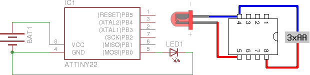
Multiplying the numbers in parentheses gives the exact length of each period, which makes it possible to write a simple sketch for an Arduino to display something simple. I chose to test with three horizontal displaying the flag of Hungary using a 66 row high light red (12), a 68 row high white (15) and a 66 row high light green (10) stripe. For the sake of simplicity, I connected the high intensity pin (6) to constant 5 volts, so the Arduino had 5 wires connected to it using the following scheme.

  • pin 1 and 2 (ground) were connected to the Arduino ground
  • pin 3 (red) was connected to Arduino digital pin 10 (bit 2 of PORT B)
  • pin 4 (green) was connected to Arduino digital pin 11 (bit 3 of PORT B)
  • pin 5 (blue) was connected to Arduino digital pin 12 (bit 4 of PORT B)
  • pin 6 (intensity) was connected to Arduino power pin 5V
  • pin 7 (reserved) was left floating
  • pin 8 (horizontal sync) was connected to Arduino digital pin 8 (bit 0 of PORT B)
  • pin 9 (vertical sync) was connected to Arduino digital pin 9 (bit 1 of PORT B)

Those who used Arduino digitalWrite exclusively, might not know what PORT B is – if you're not one of them, you can skip this paragraph. The AVR microcontroller used in the Arduino has its I/O pins grouped into 8-bit registers that are mapped into the memory, thus accessible via certain variables, for example assigning an 8-bit value to PORTA writes the bits given to digital pins 0 to 7 in one quick step. In most cases, there's no need to get into this, but in timing-critical cases as this, there's significant advantage in accessing the hardware directly – see for yourself in Bill Grundmann's thorough blog post. You can read more about this direct access on the official Arduino page about port registers.

As you can see, I arranged all five pins to be connected to the low five bits of PORT B, which means that I can modify all their values in a single instruction. At the beginning of my sketch, I used #defines to provide constants named in a meaningful way.

#define HSYNC 1
#define VSYNC 2
#define RED 4
#define GREEN 8
#define BLUE 16
#define WHITE (RED | GREEN | BLUE)
#define BLACK 0
#define COLOR WHITE
#define ROWS 261

In the setup function, the sketch initializes the output ports and sets all output pins to low.

void setup() {
    DDRB |= HSYNC | VSYNC | COLOR;
    PORTB &= ~(HSYNC | VSYNC | COLOR);
}

There are also two global variables used to track the color of the current stripe (rgb) and the number of the current row (row).

int row = ROWS;
byte rgb = BLACK;

In the loop function, the sketch draws a single row. It begins with the left blanking and overscan area that takes around 6.7 μs, then sets the R-G-B pins to the color of the current stripe. The width of the visible area is 640 pixels that take approximately 44.69 μs, after that, all R-G-B pins are reset to low.

delayMicroseconds(6);
PORTB |= rgb;
delayMicroseconds(44);
PORTB &= ~COLOR;

The right overscan and blanking take around 7.8 μs, after that, HSYNC needs to be pulled high for approximately 4.47 μs.

delayMicroseconds(8);
PORTB |= HSYNC; // HSYNC HIGH
delayMicroseconds(4);
PORTB &= ~HSYNC; // HSYNC LOW

At the end of the row, the row-level logic increments the row counter and uses a switch statement to handle certain rows specially. The first three cases cover the flag generation: after the 66th row, the color changes to white, at the 134th it does again to green, and at the bottom of the screen, color gets turned off. Between the 225th and the 228th row, VSYNC is set to high, and after the last row, the row counter gets reset to zero.

switch (row++) {
    case 66:
        rgb = WHITE;
        break;
    case 134:
        rgb = GREEN;
        break;
    case 200:
        rgb = BLACK;
        break;
    case 225:
        PORTB |= VSYNC; // VSYNC HIGH
        break;
    case 228:
        PORTB &= ~VSYNC; // VSYNC LOW
        break;
    case ROWS:
        rgb = RED;
        row = 0;
        break;
}

The actual delay values seen in the snippets above are the results of rounding and testing as the Arduino libraries hook certain interrupts making it difficult to predict the actual execution time of the code. Because of this, I measured the horizontal sync frequency with my multimeter and adjusted the values so that the HSYNC frequency is around 15.65 kHz (instead of 15.75 kHz). It almost worked for the first time – I forgot to put #define WHITE into parentheses causing the negate operator (~) to behave in an unexpected way. After fixing that, it worked perfectly for a proof of concept, as it can be seen on the photo below.

Arduino driving a CGA display to display the Hungarian flag

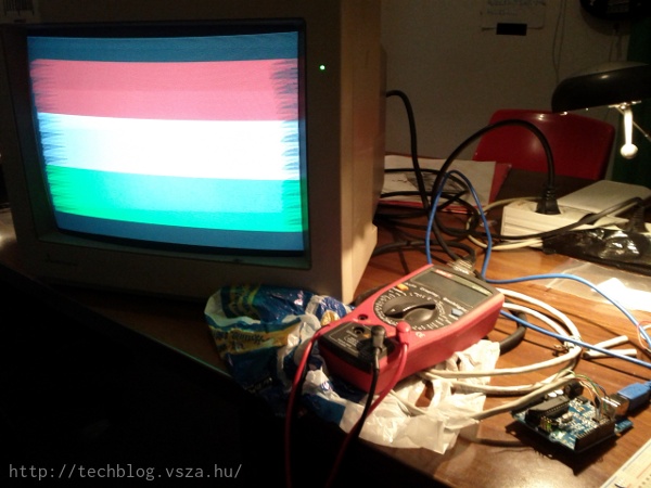
The weird edges are caused by the improper timing, so the next step will be to use plain AVR C/C++ code to avoid Arduino overhead allowing finer control over the timing. As the RAM of the Atmega168 is far too small for a framebuffer, I have plans to create a character map in the Flash (PROGMEM) and create a library that would allow to display any text or simple graphics. I hope you enjoyed this post, hold on till the next part, or better grab a CGA display and start experimenting!


CC BY-SA RSS Export
Proudly powered by Utterson