October 2013 update: added photos and corrected STK500 pinout
After visiting a new hobby craft shop, we decided to create a picture frame with a seashore theme, which included a lighthouse. I thought it would be nice to include a pulsating light to make it more realistic - and providing me with a challenge while Judit did the rest of the frame.
When I got my Atmel STK500, the guy I bought it from gave some AVR MCUs with it, so I preferred to use one of these instead of buying one. Based on size and the number of pins, I selected an ATtiny22, which could be used without an external oscillator at 1 MHz, which was more than enough for me. On the other hand, the ATtiny22 didn't have PWM, which meant that I had to do it from software. The hardware setup was the following.
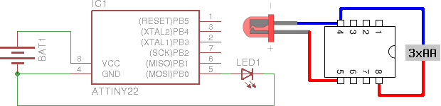
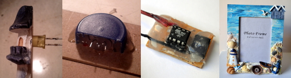
An LED was put through the lighthouse after some drilling, and the pins were routed through the frame, protected by a plastic bottle cap whose 20% was cut. The controller was put on a board with a socket on the side for the LED pins, the completely painted final version is on the right.
Since I used PB0 to drive the LED, I defined the bit I had to use as
LED_PIN, with the value 20 = 1. I used this first when I set
the direction register (DDR) of port B to use PB0 as output.
DDRB |= LED_PIN;
The rest of the program is an endless loop that does the pulsating in two similar phases, increasing the duty cycle of the PWM from minimum to maximum and then doing the same in reverse.
uint8_t level, wait;
while (1) {
    for (level = 0; level < 255; level++) {
        for (wait = 0; wait < HOLD; wait++) {
            sw_pwm(level);
        }
    }
    for (level = 255; level > 0; level--) {
        for (wait = 0; wait < HOLD; wait++) {
            sw_pwm(level);
        }
    }
}
I defined HOLD to 16 based on experimentation, this value determines how
long the light stays at a specific brightness level, so lowering this
would make the frequency of the pulsating higher. I defined the actual PWM
logic in an inlined function called sw_pwm that executes an amount of
NOP instructions related to the PWM duty cycle and toggles the port
state using the PORTB register.
inline static void sw_pwm(uint8_t fill) {
    uint8_t ctr = 0;
    for (ctr = 0; ctr < fill; ctr++) {
        asm("nop");
    }
    PORTB ^= LED_PIN;
    for (ctr = fill; ctr != 0; ctr++) {
        asm("nop");
    }
    PORTB ^= LED_PIN;
}
Compilation and conversion to Intel hex was pretty straightforward using GCC.
$ avr-gcc main.c -o main -O2 -DF_CPU=1000000 -mmcu=attiny22
$ avr-objcopy -j .text -j .data -O ihex main main.hex
Flashing however required two things to be taken care of.
AVRdude doesn't know about ATtiny22 by this name, however, the man page states that “AT90S2323 and ATtiny22 use the same algorithm”, so I used
2343as the parameter to the-p(part) command line switch.As David Cook wrote on the Robot Room ATtiny tutorial, using STK500 not only requires putting the ATtiny22 into the rightmost blue socket, but two additional pins needs to be connected: PB3 to XT1 and PB5 to RST.
Having done the above, the following command uploads the hex to the ATtiny.
$ avrdude -p 2343 -c stk500 -P /dev/ttyUSB0 -U flash:w:main.hex
Below is a photo of the completed product, click on the image to view an animated GIF version, source code is available under MIT license in my GitHub repository.